Super-Simple Skeleton Building and Animation Tutorial
Author's Note, 29 May 2012: Looking for an animation tutorial? This one is next to useless. It was intended to show how statues can be made into enemy creatures without having them move. For a full-blown animation tutorial, check out my blog post here.
 In my last blog post, I showcased my latest 3D model, a statue of an elven warrior. It’s perfectly fine as a placeable, but Dirtywick wanted me to make it a creature. The statue is supposed to be some kind of magical defense against intruders, but there seem to be problems with trying to get placeables to be targeted by NPCs and to fire visual effects without resorting to a bunch of workarounds. Dirtywick wanted to keep things simple for the area designers on our team, which leaves me with the burden of providing a solution. In this particular case, one solution is for the statues to be implemented as creatures that can shoot spells from the crystals they are holding. None of the existing skeletons and animations in NWN2 is suitable for our needs, however, so I took this as an opportunity to teach myself how to make skeletons and animations from scratch. As usual, I’m documenting the things that I’ve learned in a tutorial.
Its title notwithstanding, this blog post is not a super-simple tutorial on skeleton building and animation. This is a tutorial on building and animating a super-simple skeleton. The skeleton will consist of only one bone and a few attachment points. It will have only one idle animation that does absolutely nothing. The animation is for a statue after all. It’s not supposed to fidget while it stands in place. Nevertheless, the statue will be able to shoot spells from the crystal it is holding, and because it is effectively a creature, NPCs will be able to target it for destruction without any changes to their AI.
Preliminaries
It is assumed that you have 3DS Max version 6, 7, or 8 as well as the Expotron plug-in that Obsidian Entertainment used in developing NWN2. This plug-in will not work with any other version of Max, nor will it work with other 3D modeling software. (The Expotron plug-in used to be available at the Vault but has since been removed because of legal issues. If you happened to download it before it was removed, lucky you.) It is also assumed that you’ve already constructed and textured the main skin mesh of your model as well as its two lower level-of-detail meshes. The third and final assumption is that you know how to rig the mesh with the new skeleton that you’ll be creating.
It’s important to name your meshes properly. For creature models that are neither PCs nor NPCs, the main mesh should be named C_name_ar_BODYxx, where name is a unique identifier for your model, ar is the type of armor your model is wearing (CL if the model is unarmored), and xx is a two-digit number from 01 to 99. Mesh names are not case-sensitive.
If, like me, you’ve been using Tazpn’s plug-in to import MDB models as a reference for setting the scale of your models, the Expotron will export them at a very tiny scale. You should resize your meshes at 10,000% of the scale that Tazpn’s plug-in works with. After rescaling, you should make sure that the base of each mesh is at world coordinate (0, 0, 0).
Skeleton Building
Exporting the Skeleton
You are now ready to use the Expotron. The first thing to do is to export the skeleton.
Exporting an Animation
Every skeleton needs at least one animation – the idle animation. Since our statue model will not move a muscle while it is idle, this section is going to be easy.
Exporting the Model
Testing Your Model
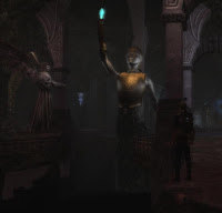
Below are screenshots that demonstrate that the statue’s spells do shoot out from its crystal. In each picture, one of the statues is a placeable, and the other is a creature. It's easy to guess which is which.
Acknowledgments
This blog post is based in part on the document Exporting Animated Creatures by Jay Bakke of Obsidian Entertainment. Even if you've already read this document, my blog post has some important information that you won't find there.
The screenshot shown at the beginning of this blog post was made by E.C. Patterson, aka ciViLiZed. I emailed him a copy of my placeable statue model, and he sent me back this picture. I love the way he lit the area in the screenshot. It highlighted the etching on the statue's breastplate very well.
Edit, 30 March 2012. Thanks also to Eguintir Eligard for pointing out some errors in the text on exporting animations. I have since corrected the text.
Edit, 3 May 2012. I removed the dead link to the Expotron and added some explanatory text on why it disappeared from the Vault.
 In my last blog post, I showcased my latest 3D model, a statue of an elven warrior. It’s perfectly fine as a placeable, but Dirtywick wanted me to make it a creature. The statue is supposed to be some kind of magical defense against intruders, but there seem to be problems with trying to get placeables to be targeted by NPCs and to fire visual effects without resorting to a bunch of workarounds. Dirtywick wanted to keep things simple for the area designers on our team, which leaves me with the burden of providing a solution. In this particular case, one solution is for the statues to be implemented as creatures that can shoot spells from the crystals they are holding. None of the existing skeletons and animations in NWN2 is suitable for our needs, however, so I took this as an opportunity to teach myself how to make skeletons and animations from scratch. As usual, I’m documenting the things that I’ve learned in a tutorial.
Its title notwithstanding, this blog post is not a super-simple tutorial on skeleton building and animation. This is a tutorial on building and animating a super-simple skeleton. The skeleton will consist of only one bone and a few attachment points. It will have only one idle animation that does absolutely nothing. The animation is for a statue after all. It’s not supposed to fidget while it stands in place. Nevertheless, the statue will be able to shoot spells from the crystal it is holding, and because it is effectively a creature, NPCs will be able to target it for destruction without any changes to their AI.
Preliminaries
It is assumed that you have 3DS Max version 6, 7, or 8 as well as the Expotron plug-in that Obsidian Entertainment used in developing NWN2. This plug-in will not work with any other version of Max, nor will it work with other 3D modeling software. (The Expotron plug-in used to be available at the Vault but has since been removed because of legal issues. If you happened to download it before it was removed, lucky you.) It is also assumed that you’ve already constructed and textured the main skin mesh of your model as well as its two lower level-of-detail meshes. The third and final assumption is that you know how to rig the mesh with the new skeleton that you’ll be creating.
It’s important to name your meshes properly. For creature models that are neither PCs nor NPCs, the main mesh should be named C_name_ar_BODYxx, where name is a unique identifier for your model, ar is the type of armor your model is wearing (CL if the model is unarmored), and xx is a two-digit number from 01 to 99. Mesh names are not case-sensitive.
If, like me, you’ve been using Tazpn’s plug-in to import MDB models as a reference for setting the scale of your models, the Expotron will export them at a very tiny scale. You should resize your meshes at 10,000% of the scale that Tazpn’s plug-in works with. After rescaling, you should make sure that the base of each mesh is at world coordinate (0, 0, 0).
Skeleton Building
 Hide the two lower level-of-detail meshes so that only the main mesh is visible. With the main mesh selected, go to the Display panel at the right of the screen and click the “See-Through” box to put a check mark in it. This will make it easier to position bones and attachment points in relation to the mesh.
 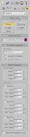 Go to the Create panel and click the Systems button, which is the rightmost button just below the panels’ tabs. Under “Object Type,” click the Bones button.
 Click successive points in one of the viewports to create bones. We only want to create one bone, so press the [Esc] key after clicking two points. This will actually create two bones, so select the longer bone and delete it. Rename the remaining bone using the following convention: C_name_SKEL, where name is the unique identifier of your model. This bone will be the root node of your skeleton hierarchy, which includes not only bones but also attachment points and collision spheres.
 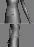 Move the bone you created to the desired position. This is almost always the center of the pelvic area.
 - We’re going to create and position a few attachment points, which are sort of like invisible hooks to which other external objects can attach themselves. All attachment points are prefixed with “ap_”. In NWN2, there is a standard set of attachment points with specific names. The ones that we’re going to use are the following:
Attachment Point Name Usual Position Example Attachment Objects ap_camera Inside the head The camera’s focal point during cutscenes when the creature is the active speaker ap_halo Above the head Effect icons, spell conjuration effects ap_hand_right Right hand Primary weapons, spell conjuration effects ap_torso Center of and just behind the chest Spell conjuration effects
I chose these attachment points because they are the ones most likely to be used for spellcasting and cutscenes. For the statue model, I want to change the position of ap_halo to just above the crystal and ap_hand_right to inside the crystal. Both of these attachment points are involved in spell conjuration and casting, and I want to make the statue’s spells seem to emanate from the crystal.
 In 3DS Max, attachment points are implemented as dummy objects. In the Create panel, click the Helpers button then click the Dummy button.
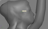 Click and drag the mouse icon over a tiny area of a viewport to create a dummy object. Change the name of the object to one of the standard attachment point names and set its desired position. Do this for all attachment points before moving to the next step.
  Nearly all creature models have one or more collision spheres, and this statue is no exception. Collision spheres are for determining if two objects are in contact with each other or if there is a straight line of sight toward an object. In NWN2, only creature objects make use of collision spheres. (Placeables make use of collision boxes.) Each collision sphere is attached to a single bone and moves with that bone. Generally, a collision sphere encompasses the bone to which it is attached.
To create a collision sphere, click the Geometry button in the Create panel. Click the Sphere button and click-and-drag the mouse cursor in any of the viewports to create a sphere of the desired size. Adjust the position of each sphere if necessary. The first collision sphere should always be named “COLS00.” Subsequent spheres are named “COLS01” to “COLS99.” Select each sphere in turn and edit its Object Properties. Make sure that the “See-Through” box is checked and that the Renderable box is not checked. When you’re done, click the OK button to close the Object Properties window.
 - Having created all the bones, attachment points, and collision spheres that we need, our next step is to arrange them in a skeleton hierarchy. In this example, the process is very easy because we have only one bone, one collision sphere, and four attachment points to connect. All of the attachments points as well as the collision sphere are connected to the bone, which is the root node by default. Hence, in our hierarchy, the bone is the lone parent object, and the attachment points and the collision sphere are its direct child objects.
 Select a child object then click the “Select and Link” button, which is the third button at the bottom of the main menu.
 Move the cursor to the chosen child object then click the mouse button without releasing it. Drag the cursor to the parent object, which in this case is the only bone in this model. A dotted line should stretch out as you drag the cursor. With the cursor over the parent object, release the mouse button. The white outline of a square will flash briefly around the parent object to indicate that a link was created between the two objects. Repeat this process for all the other child objects.
 Sometimes, it’s difficult to link objects in this manner, especially if one object encompasses or is very near the other. If that is the case, first make sure that the “Select and Link” button is not pressed then select the child object that you want to connect. Now click the “Select and Link” button and press the [H] key. This will bring up the “Select Parent” dialog box. Click the name of the object that you want to set as the parent then click the Link button at the bottom of the dialog box. This will cause the two objects to be linked.
  Optional step: If you want to make sure that you linked the objects correctly, press the “Schematic View” button, which is one of the rightmost buttons just under the main menu bar. This will open a Schematic View window. You should see a hierarchical view with the root bone at the top and the child objects below it. The three skin meshes are independent of this hierarchy and are not connected to it. Close the Schematic View window when you’re done.
 - Rig each of the skin meshes with the bones that you created. I won’t go into detail in this step, having already explained this process elsewhere in my blog.


Exporting the Skeleton
You are now ready to use the Expotron. The first thing to do is to export the skeleton.
 Select all the bones and attachment points of the model. The easiest way to do this is to press the [H] key to bring up the Select Objects dialog box and press [Ctrl]+mouse click on each object that you want to select. Click the Select button at the bottom of the dialog window when you’ve selected all the bones and attachment points.
 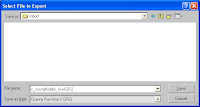 In the File menu, select the “Export Selected…” option. This will bring up a dialog box for you to enter the name and type of the file to export. Under “Save as Type,” choose “Granny Run-Time (*.GR2)”. The name of the file that you enter should be the same as the name of the root bone node. Click the Save button.
 - In the Granny Export Settings window, click Models. Make sure that the box beside “Include reference in export” is checked and that the box beside “Move to Origin” is not checked. Click the Export button at the bottom of the window.


Exporting an Animation
Every skeleton needs at least one animation – the idle animation. Since our statue model will not move a muscle while it is idle, this section is going to be easy.
 Press the Auto Key button near the bottom of the screen.
Normally, at this stage, you would be setting frames and moving and rotating bones into position at each frame. Nevertheless, our model will be as lifeless as a rock, so we’re done with making its idle animation. Select all the bones and attachment points of the model. In the File menu, select the “Export Selected…” option. This will bring up a dialog box for you to enter the name and type of the file to export. Under “Save as Type,” choose “Granny Run-Time (*.GR2)”. Name the file to export C_name_IDLE, where name is the unique identifier of the model. Press the Save button to continue.
 - In the Granny Export Settings window, click Animations. Make sure that the box beside “Include reference in export” is checked and that the box beside “Move to Origin” is not checked. Slide the Oversampling button all the way to the right then set “orientation curve tolerance” to 0.15. Click the Export button at the bottom of the window. When the animation has been exported, click the Close button.
- If there are other animations you wish to make, you may repeat steps 13 to 15 for each animation file. Release the Auto Key button when you’re done. My advice, however, is to defer creating anything other than the idle animation until you’ve checked your model in the toolset. This is because you may have to correct the coordinates of ap_camera and ap_halo first.


Exporting the Model
 We’re now about to export the model to an MDB file. If the main mesh is see-through, uncheck the see-through display option. Unhide all the lower level-of-detail meshes if they are hidden. Now select all the skin meshes.
 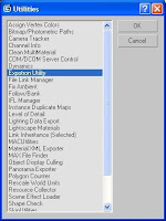 Go to the Utilities panel. If you don’t see Expotron among the list of utilities, click the More button and select “Expotron Utility” from the list that appears.
  Under “NWN2 Types,” click the button beside “Character (skin).” If your mesh will be using transparencies, click the button beside “Transparency Mask” under “NWN2 Flags.” Otherwise, make sure that the button beside “No Transparency” is selected.
  Under “Skeleton Name,” type the name of the skeleton file that you created for your model.
  Add all collision spheres to the list of currently selected objects.
  In the File menu, select the “Export Selected…” option. This will bring up a dialog box for you to enter the name and type of the file to export. Under “Save as Type,” choose “Neverwinter Nights 2 (*.MDB)”. Under “File Name,” type the name of your main mesh then click the Save button. In the Expotron Export Options window, make sure that all the boxes are checked then click the OK button.


Testing Your Model
 Copy your MDB and two GR2 files to the folder “My Documents\Neverwinter Nights 2\override”. Copy the appearance.2DA file to your override folder and add an entry for your model. Create a new module in the toolset and add a creature blueprint for your model. Add an area to the module, and put your creature on it. Make sure that the Skeletons button, which is below the main menu bar of the toolset, is pressed. Now examine the creature and its skeleton. Notice any problems?
If you find that ap_camera and ap_halo are in their proper positions, go ahead and create the rest of the animations that this creature will need, if any. Otherwise, you’ll have to change the coordinates of these two attachment points. The Expotron does not seem to export the position of ap_camera and ap_halo correctly. To the best of my knowledge, this problem was first reported by Schazzwozzer at the NWN2 forums on December 3, 2007. At the time that he reported the problem, no one came up with a solution. I believe I have found a solution to this problem, which I will explain below.- We’re going to work with the creature model in 3DS Max again. Select ap_camera and ap_halo in turn and write down their exact x, y, and z coordinates.
Now for these two attachment points, exchange the x-coordinate with the z-coordinate. You may have to add a number to the three coordinates of each attachment point as well. I can’t say for sure what those numbers should be for any given model. I had to go through a process of trial-and-error to find the numbers that I needed to add for the model I made. The following are the formulas I used to derive the new coordinates:
New X-Value New Y-Value New Z-Value ap_camera Old_Z + 115 Old_Y + 20 Old_X + 5 ap_halo Old_Z + 50 Old_Y + 10 Old_X
 Each time you change the coordinates of either or both these attachment points, you’ll have to re-export the skeleton and possibly the idle animation of your model to your override folder. You’ll be able to check out your model in the toolset to see if ap_camera and ap_halo are in their proper positions. If the above formulas don’t work for you, you’ll have to experiment with the values to add to each coordinate. If all goes well, you’ll see that ap_camera and ap_halo are in the exact position that you want them to be.
 - The iron test for any creature model is to check it out in the game. Bake the area of your test module and prepare for a few encounters with your creature.


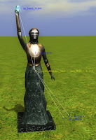
Below are screenshots that demonstrate that the statue’s spells do shoot out from its crystal. In each picture, one of the statues is a placeable, and the other is a creature. It's easy to guess which is which.
 |  |
 |  |
Acknowledgments
This blog post is based in part on the document Exporting Animated Creatures by Jay Bakke of Obsidian Entertainment. Even if you've already read this document, my blog post has some important information that you won't find there.
The screenshot shown at the beginning of this blog post was made by E.C. Patterson, aka ciViLiZed. I emailed him a copy of my placeable statue model, and he sent me back this picture. I love the way he lit the area in the screenshot. It highlighted the etching on the statue's breastplate very well.
Edit, 30 March 2012. Thanks also to Eguintir Eligard for pointing out some errors in the text on exporting animations. I have since corrected the text.
Edit, 3 May 2012. I removed the dead link to the Expotron and added some explanatory text on why it disappeared from the Vault.


Comments
I think this goes beyond my patience levels ... or may be something I would consider a few months down the line. :)
Lance.
I'm using MAX 2009 i can't export animation... :(
I hope they release something to max 9, 2009, 2010, blender, maya. If they do we will see more things.
Obsidian should fear release more tools because the community can do better than them