Creature Modeling, Part 5: Normal Mapping
This is a continuation of my series on building creature models for NWN2. Those who haven’t read the start of the series may want to refer to my previous blog posts.
 Having created a UVW map for our model, we can now texture it. The NWN2 engine uses four kinds of texture maps for its models:
Of these four types, only the Diffuse and Normal maps are required for all models. This blog post will show how a normal map may be created. In broad terms, the steps to be done are the following:
A. Creating a High-Poly Model
You can use any modeling software to create a high-poly version of your low-poly mesh. Here, I’ll explain how to do it with ZBrush.
B. Mapping the High-Poly to the Low-Poly Model
C. Testing the Normal Map
Is it worth the effort to make highly detailed normal maps for your models? Let your eyes be the judge.
Normal maps can make low-poly models look far more complex than they really are. Nevertheless, without properly applied color, even highly-detailed models will look drab at best. In my next blog post, I’ll show how to create diffuse and glow maps for the creature we’re building.
Edit, 3 May 2012. I edited this blog post to include a step on inverting the red channel of the normal map (step 19).
 Having created a UVW map for our model, we can now texture it. The NWN2 engine uses four kinds of texture maps for its models:
- Diffuse – Diffuse maps, along with tint maps, set the colors of an object. In the absence of a tint map, the diffuse map will completely determine what colors an object has.
- Normal – Normal maps are used for making low-poly objects look more high-poly. Normal maps seem to raise or lower the surface of an object like carvings on a bas relief. This is done without straining the graphics engine the way a high-poly model would.
- Glow – Glow maps identify what parts of an object glow and how intensely they glow.
- Tint – Tint maps identify which parts of an object may be tinted. Tint maps will not be discussed in this tutorial because the creature I’m making doesn’t need one. Those who want to know more about this topic may read what Heed has to say.
Of these four types, only the Diffuse and Normal maps are required for all models. This blog post will show how a normal map may be created. In broad terms, the steps to be done are the following:
- Create a detailed, high-poly version of the model.
- Map the high-poly model to the low-poly model.
- Check the low-poly model in the toolset for any problems the normal map may have.
A. Creating a High-Poly Model
You can use any modeling software to create a high-poly version of your low-poly mesh. Here, I’ll explain how to do it with ZBrush.
- Run 3DS Max and load the MAX file that you worked on during your last session. Click the head mesh to select it then go to the “File” menu and click “Export Selected…” Export the mesh as a Wavefront Object.
- Run ZBrush and import the OBJ file that you had saved.
 We’re about to subdivide the mesh, but before we do, we need to “crease” it. In the “Tool” menu, click “Geometry” then click the “Crease” button. This will prevent ZBrush from creating wavy edges around parts of the mesh that have holes in them.
 - Subdivide the mesh by pressing [Ctrl]+D three or four times. This will add more polygons to the mesh.

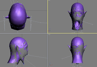
- Embellish the high-poly model with as many details as you like.

- Export the mesh as a Wavefront Object.


B. Mapping the High-Poly to the Low-Poly Model
- If you aren’t running 3DS Max anymore, run it and load the MAX file you’ve been working on.
- Import your high-poly model. Make sure that the low and high-poly models overlap as closely as possible. Note that loading the high-poly model may take a while. The one shown here took 17 minutes to load on my computer.
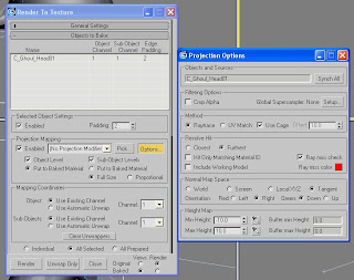
 Select the low-poly model then press the [0] key. This will cause the “Render to Texture” dialog box to appear with the low-poly model already selected.
 Click the box under “Projection Mapping” beside “Enabled” to put a checkmark in it. Under “Mapping Coordinates,” click the button beside “Use Existing Channel” for both “Object” and “Sub-Objects.”
  Click the button labeled “Pick…,” which is under “Projection Mapping.” This will cause the “Add Targets” dialog box to appear. From the list on the left side of the window, click the name of the high-poly mesh you had imported then click the “Add” button. The “Add Targets” window will then close. Note that a “Projection” modifier is automatically added to your low-poly model. We’ll deal with this modifier later.
 - Click the button labeled “Options…” This will bring up the “Projection Options” dialog box. Under “Filtering Options,” click the “Setup…” button to bring up a new dialog box.
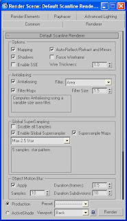 In the new dialog box, look under “Global SuperSampling” and click the box beside “Enable Global Supersampler” to put a checkmark in it. Close the dialog box then close the “Projection Options” window.
 - Scroll down the window until you see the “Add” button under “Output.” Click the button. In the dialog box that appears, click “NormalsMap” then click the “Add Elements” button. This will cause the dialog box to close.

 Scroll further down the “Render to Texture” window until you see six buttons under “Use Automatic Map Size.” Click the button that corresponds to the size in pixels of the normal map to be generated. For my model, I chose 512, which is good enough for run-of-the-mill monsters. While you’re at it, set the list box labeled “Target Map Slot” to “Bump.”
 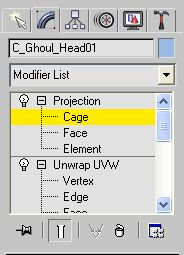 Go to the Modifier panel. (You don’t have to close the “Render to Texture” window just yet.) Click the “+” sign beside the “Projection” modifier to expand it then click “Cage.”
  Scroll all the way down the Modifier panel then click the “+” sign beside the “Cage” rollout to expand it. Now click the “Reset” button. Under “Push,” click the button with the upward-pointing arrowhead beside “Amount” until the blue “cage” completely surrounds the model as seen in the viewports.
- Click the “Render” button at the bottom of the “Render to Texture” window. (If you closed it earlier, press the [0] key to bring it back.) This will cause a normal map in TGA format to be output to the Image folder in your Autodesk\3dsMax installation.

- Because the way NWN2 interprets normal maps is slightly different from that of 3DS Max, we need to invert the red channel of the normal map. Edit your normal map in your preferred image editor. If you are using Photoshop, click the Channels tab on the right of the screen then click the channel labeled "Red" and press [Ctrl]+I to invert it. Click the channel marked "RGB" to return to RGB mode and save your normal map.
- You may convert your normal map to a DDS file (DXT5) with 9 mipmaps using an image converter program. (The first part of my tutorial series mentions a couple of free ones that you may download.) 3DS Max also has an option to output the normal map directly as a DDS file, but to the best of my knowledge, you won’t have any control over the number of mipmaps generated.
When you’re done, move the DDS file to the NWN2 override folder. You may now close the “Render to Texture” window.


C. Testing the Normal Map
 Select your low-poly mesh and press the [M] key to bring up the Material Editor. Assign your new normal map to the Bump material of the model. Close the Material Editor when you’re done.
 - Export the model as an MDB file. Make sure that the file name matches the name of the model. Copy the file to your NWN2 override folder.
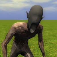
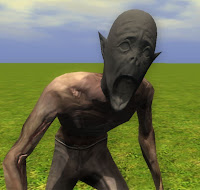 Run the toolset and create a small exterior area. Put a ghoul in the area and zoom in on it. Because we’re modifying the ghoul model as a quick way to test the creature we’re making, we should see the creature’s head on the ghoul body. Make sure that the new normal map displays properly on the creature’s head.
 - If you notice any problems with the normal map, you may have to correct it in 3DS Max. Once the normal map meets your approval, delete the high poly mesh from your model and save it as a MAX file.

Is it worth the effort to make highly detailed normal maps for your models? Let your eyes be the judge.
|  |
| Before | After |
Normal maps can make low-poly models look far more complex than they really are. Nevertheless, without properly applied color, even highly-detailed models will look drab at best. In my next blog post, I’ll show how to create diffuse and glow maps for the creature we’re building.
Edit, 3 May 2012. I edited this blog post to include a step on inverting the red channel of the normal map (step 19).


Comments
These look like some great tutorials. I recognise now that you need to put aside a whole slot of time to do what you are doing though.
Once complete, have you thought about putting it into a manual and uploading it to the Vault?
This would have been very useful for when I was looking a while back.
Lance.
http://img208.imageshack.us/img208/237/phhmhead84n3ds.jpg
Anyhow, I can't access your pic. This is all I see.