Creature Modeling, Part 4: UVW Mapping
This is a continuation of my series on building creature models for NWN2. Those who haven’t read the start of the series may want to refer to my previous blog posts.
In my last blog post, I showed an overly simple way to texture a 3D model. This method is good only for quickly testing the model in the NWN2 engine. We’ll need to do better than that for in-game use, however.
Before we can apply textures, though, we need to provide our model with a UVW map. This map tells graphics engines which pixels to paint over which parts of the mesh. For some humanoid heads, the mapping technique I showed in my last blog post may suffice. Nevertheless, this method is inadequate for the creature head that has been the subject of this series.
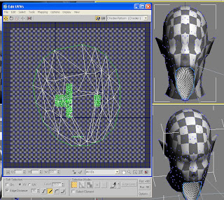
 The screenshot to the right illustrates the perils of improper UVW mapping. The mouth’s texture has bled into the neck of this creature. I originally applied a cylindrical UVW map, which I had explained how to do in my previous blog post. The results were disastrous. This model requires a more complicated approach to UVW mapping. We’ll use a technique called Pelt Mapping for this. The following steps explain how to do it.
Using the “Unwrap UVW” modifier, we were able to apply a powerful technique called pelt mapping. This technique is much more complicated than simply using the “UVW Mapping” modifier, but it also gives you greater control over the outcome.
Now that the model has a UVW map, we’ll create some textures for it. I’ll discuss texturing in my next post in this series.
In my last blog post, I showed an overly simple way to texture a 3D model. This method is good only for quickly testing the model in the NWN2 engine. We’ll need to do better than that for in-game use, however.
Before we can apply textures, though, we need to provide our model with a UVW map. This map tells graphics engines which pixels to paint over which parts of the mesh. For some humanoid heads, the mapping technique I showed in my last blog post may suffice. Nevertheless, this method is inadequate for the creature head that has been the subject of this series.
 The screenshot to the right illustrates the perils of improper UVW mapping. The mouth’s texture has bled into the neck of this creature. I originally applied a cylindrical UVW map, which I had explained how to do in my previous blog post. The results were disastrous. This model requires a more complicated approach to UVW mapping. We’ll use a technique called Pelt Mapping for this. The following steps explain how to do it.
 Run 3DS Max and load the MAX file that you worked on during your last session. (You did save it, didn’t you?) Click on the model to select it then click the tab on the Modifier panel. We’re going to remove the UVW map that we created last time, so right-click the “UVW Mapping” modifier and click “Delete” on the context-sensitive menu.
Don’t make the mistake of clicking the “UVW Mapping” modifier and hitting the [Delete] key. That will delete your model entirely. In case you did, press [Ctrl]+Z to undo the mistake. Click the downward-pointing arrowhead in the “Modifier List” box and select “Unwrap UVW.” You’ll have to scroll all the way down the list to find it.
 In the list of modifiers, click the “+” sign beside “Unwrap UVW” to expand it then click “Edge.”
 Scroll all the way down the Modifier panel and click the “Edit Seams” button.
- Click the model if it isn’t already selected then right-click it. From the context-sensitive menu, click “Properties.” This will bring up the “Object Properties” dialog box. In the “Display Properties” section, make sure that the box beside “Vertex Ticks” is checked. If it isn’t, click the box to put a check on it. Click the “OK” button to close the window. You should now see tiny blue square-shaped dots around the mesh. These dots mark the position of the vertices in the mesh.

- Select the Back viewport and zoom in to focus on the creature’s mouth. (Remember that the Back view actually shows the model’s face.) You’re about the trace a seam around the edges of the mouth, so be sure to get a nice close-up. If the mesh is displayed in wireframe mode, press the [F3] key to switch to smooth + highlights mode.

- Click each edge at the periphery of the creature’s mouth. An edge is a line segment that is between two vertices, so click the space between a pair of vertices to select the edge. Each time you do this, a cyan-colored line will appear, marking the edge that you clicked. This edge is a seam that we will use for pelt mapping later. Keep doing clicking edges until the entire periphery of the mouth is marked with cyan. If you make a mistake in selecting an edge, press [Ctrl]+Z to undo the action.

 Let’s return our attention to the Modifier panel. In the list of modifiers under “Unwrap UVW,” click “Face.” When this option is activated, clicking a polygon will select it.
- Set up your viewports so that you can see the Bottom and Back views of the model. Both views should be in smooth + highlights mode. Now hold down the [Ctrl] key and click each polygon inside the mouth to select it. Make sure that only the polygons that are within the seams that you had created earlier are selected. You’ll need to click the interior of the mouth as seen in the Bottom view to select the palate.

 Scroll down the Modifier panel and click the “Pelt” button, which is in the “Map Parameters” rollout. Click the “Best Align” button as well.
- Click the “Edit Pelt Map” button, which is at the bottom of the “Map Parameters” rollout. This will cause two windows to appear, one called “Edit UVWs” and another called “Pelt Map Parameters.”

- In the “Edit UVWs” window, there is a box with the words “CheckerPattern (Checker).” Click the downward-pointing arrowhead in the box then click “CheckerPattern (Checker)” in the drop-down list. This will cause the mesh to be textured with a checker pattern, which is very useful for testing UVW maps. You’ll want to keep the distribution of checker patterns even within the map to avoid texture distortion. In the picture shown below, the UVW map is in bad need of improvement. For now, we’ll concentrate on the inside of the mouth and ignore everything else.
Go back to the “Pelt Map Parameters” window and click the “Simulate Pelt Pulling” button a few times. This will stretch the UVW map like an animal pelt being stretched over a frame. Don’t click the button too often however because you risk distorting the UVW map. See how the checker pattern is distributed in the mesh to gauge whether you’ve clicked the button too many times. Remember that you can always undo your action by pressing [Ctrl]+Z. Close the “Pelt Map Parameters” window when you’re done. - At the bottom of the “Edit UVWs” window is a squared-off section labeled “Selection Modes.” Click the “Face Sub-object Mode” button (the third one from the left) and make sure that the box labeled “Select Element” is checked. If the UVW map of the mouth is not highlighted in red, click it to select it.

- Click the “Relax Dialog” option from the “Tools” menu of the “Edit UVWs” window. This will cause the “Relax Tool” window to appear.

The purpose of this tool is to minimize distortion in your texture maps. You can experiment with setting different parameters in this window and clicking the “Apply” button. Check the viewports to see how the checker pattern is distributed inside the model’s mouth. You may have to click the “Apply” button several times before you’re satisfied with the results. If the options you’re using aren’t working out, you may undo your actions by pressing [Ctrl]+Z as often as necessary. You may then select another set of options to experiment with.
When you’re done, close the “Relax Tool” window and the “Edit UVWs” window. Don’t be surprised to find that the checker pattern disappears when you close the latter window. That’s to be expected. - We’ve created a UVW map for the mouth interior. Next, we’ll create another map for the underside of the chin and front of the neck. Repeat steps 3 and 4 above. Next, click the edges along the underside of the chin and front of the neck to cut the seam. Much of this work will be done in the Bottom viewport, although we may work in the Left and Right viewports as well.

- In the Modifier panel, click “Face,” which you’ll find under “Unwrap UVW.” If you don’t remember where to find this option, you may want to refer to the illustration in step 8.
- Hold down the [Ctrl] key and click each polygon within the newly-created seam. The Bottom viewport is probably best for this purpose, but you’ll probably want to click polygons in the Left and Right viewports as well. Otherwise, you might miss a few of them. Either way, you may have to zoom in to make sure you don’t miss out any small polygons.

- Repeat steps 10 to 14, focusing this time on the underside of the chin and front of the neck.
- We’re now going to map the rest of the head. Under “Unwrap UVW” in the Modifier panel, click “Edge” again. Click the “Edit Seams” button then click the edges in the mesh where you want to cut a seam. In my case, I decided to cut along the side of the head, thereby dividing it between the front and back. I changed the Bottom viewport to display a top view so I could see the edges I was selecting at the top.

- Under “Unwrap UVW” in the Modifier panel, click “Face.” Now select all polygons at the back of the head.

 In the Modifier panel under “Map Parameters,” click the “Pelt” button, then click the “Best Align” button. Finally, click the “Edit Pelt Map” button and stretch the UVW map to get an even distribution of checkered patterns across rear of the model’s head.
- Select the remaining polygons that haven’t been mapped yet and repeat the process of creating a pelt map for them. You know the drill.
 In the Modifier panel, click the “Edit…” button, which is under the “Parameters” rollout. This will bring up the familiar “Edit UVWs” window.
- At this point, there are several UVW maps that need to be arranged within the square boundary of your textures. You can select each map and right-click it to bring up a context-sensitive menu. You may then choose to move the map, scale it, or rotate it. You may have to do all these operations for each map until you get a neat arrangement. Make sure that the maps do not overlap with each other unless they are supposed to share the same texture mapping.

- One last thing before we end today’s session: Save your work as a MAX file. We'll return to it later.


Using the “Unwrap UVW” modifier, we were able to apply a powerful technique called pelt mapping. This technique is much more complicated than simply using the “UVW Mapping” modifier, but it also gives you greater control over the outcome.
Now that the model has a UVW map, we’ll create some textures for it. I’ll discuss texturing in my next post in this series.
Comments