Creature Modeling, Part 3: Rigging Skin and Bones
This is a continuation of my series on building creature models for NWN2. Those who haven’t read the start of the series may want to refer to my two previous blog posts. Be warned, however, that this is the longest blog post I have written to date. You might want to get comfy before reading it.
 Now that we have a head mesh, we can begin rigging it for in-game use. First, we have to decide what skeleton should go with this model. We won’t be creating any new animations, much less any new skeletons. That’s because I haven’t figure out how to do them yet. Anyhow, the creature shown here can use any of the medium-sized humanoid skeletons that come with NWN2, so choosing one of them shouldn’t be a problem.
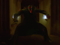
The pose of the creature as depicted in its character design is similar to the idle animation of ghouls in NWN2. Hence, I decided to recycle the ghoul skeleton for use with this creature.
Setting Up the Working Folder
Having decided on what skeleton to base the creature on, we must now set up our working folder with copies of the ghoul model, textures, and skeletons. These can be found in the Data folder of your Neverwinter Nights2 installation. For most gamers using Windows XP, the name of the folder would be “C:\Program Files\Atari\Neverwinter Nights 2\Data”. There are several zip files in this directory. The following is a list of data types and the zip files where they may be found. Note that the asterisk (*) in the file names is a wildcard that means that other characters may or may not follow.
Right now, we don’t really have much of a clue as to which files to get. To find out, we need to open the file appearance.2da, which may be extracted from 2DA.zip in your Neverwinter Nights2\Data folder. It’s easiest to read this file using a program that can separate tab-delimited data into columns. I prefer using Microsoft Excel for this, although there are free software applications at the Neverwinter Vault that can also do this.
After opening the file, we search for the row that has the word “Ghoul” under the “LABEL” column. Having found it, we need to look under the labels “NWN2_Model_Body” to find the name of the ghoul’s body model, “NWN2_Model_Head” to find the name of its head model, “NWN2_Head_Skeleton” to find the name of the skeleton that affects the ghoul’s head, and “NWN2_Skeleton_File” to get the name of the skeleton that affects the ghoul’s body. These names are c_ghoul, c_ghoul (yes, these are the same file), c_ghoul_Skel, and c_ghoul_skel. (Despite the slight difference in capitalization of the last two file names, they both refer to the same file.)
We can find the files C_Ghoul_Head01.MDB and C_Ghoul_CL_Body01.MDB in NWN2_Models.zip, and the file c_ghoul_skel.GR2 in lod-merged.zip. We should copy these files to our working directory.
We’ll also need the textures that go with the models, but we won’t find this information in any 2DA file. Instead, we’ll extract that information directly from the MDB files. Perhaps the easiest way to do this is to use RunnerDuck’s MDB Cloner. By loading the head and body model files into this software one at a time, we learn that they both use the same set of textures. We should then copy all these textures from NWN2_Materials.zip to our working folder. These textures are C_Ghoul_CL_Body01_T.dds, C_Ghoul_CL_Body01.dds, C_Ghoul_CL_Body01_I.dds, and C_Ghoul_CL_Body01_N.dds.
Rigging the Model
We’re all set, so fire up 3DS Max and do the following.
Importing and Setting Up in 3DS Max
Studying the Bones
Replacing the Head
Making It a Skin Mesh
Attaching Bones
Simplistic Texturing
Testing with NWN2
Removing Zero Weights
If you’ve read this blog post from start to finish, you probably intend to create your own creature models. If so, good for you. I hope to see your submissions at the Neverwinter Vault. Nevertheless, we’re not done yet. I haven’t explained how to texture models properly. Unless you’re happy with giving your creatures a bland, gray look, you may want to know more about texturing. That will be the topic of my next three blog posts, so stay tuned.
- Author's Note, January 20, 2009: The model shown in this write-up is not the same one that I eventually settled on. While writing this series of blog posts, I found better ways to reduce the polygonal count of my meshes. Although this post shows an older and cruder version of the model I was constructing, the workflow described is essentially the same as what I used in the final version.
 Now that we have a head mesh, we can begin rigging it for in-game use. First, we have to decide what skeleton should go with this model. We won’t be creating any new animations, much less any new skeletons. That’s because I haven’t figure out how to do them yet. Anyhow, the creature shown here can use any of the medium-sized humanoid skeletons that come with NWN2, so choosing one of them shouldn’t be a problem.
The pose of the creature as depicted in its character design is similar to the idle animation of ghouls in NWN2. Hence, I decided to recycle the ghoul skeleton for use with this creature.
Setting Up the Working Folder
Having decided on what skeleton to base the creature on, we must now set up our working folder with copies of the ghoul model, textures, and skeletons. These can be found in the Data folder of your Neverwinter Nights2 installation. For most gamers using Windows XP, the name of the folder would be “C:\Program Files\Atari\Neverwinter Nights 2\Data”. There are several zip files in this directory. The following is a list of data types and the zip files where they may be found. Note that the asterisk (*) in the file names is a wildcard that means that other characters may or may not follow.
| Zip File | Contents | File Extension |
|---|---|---|
| NWN2_Models*.zip | 3D Model files | MDB |
| lod-merged*.zip | Skeleton files | GR2 |
| NWN2_Materials*.zip | Texture files | DDS or TGA |
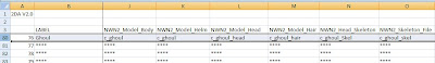
Right now, we don’t really have much of a clue as to which files to get. To find out, we need to open the file appearance.2da, which may be extracted from 2DA.zip in your Neverwinter Nights2\Data folder. It’s easiest to read this file using a program that can separate tab-delimited data into columns. I prefer using Microsoft Excel for this, although there are free software applications at the Neverwinter Vault that can also do this.
After opening the file, we search for the row that has the word “Ghoul” under the “LABEL” column. Having found it, we need to look under the labels “NWN2_Model_Body” to find the name of the ghoul’s body model, “NWN2_Model_Head” to find the name of its head model, “NWN2_Head_Skeleton” to find the name of the skeleton that affects the ghoul’s head, and “NWN2_Skeleton_File” to get the name of the skeleton that affects the ghoul’s body. These names are c_ghoul, c_ghoul (yes, these are the same file), c_ghoul_Skel, and c_ghoul_skel. (Despite the slight difference in capitalization of the last two file names, they both refer to the same file.)

We can find the files C_Ghoul_Head01.MDB and C_Ghoul_CL_Body01.MDB in NWN2_Models.zip, and the file c_ghoul_skel.GR2 in lod-merged.zip. We should copy these files to our working directory.
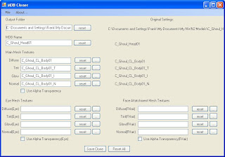
We’ll also need the textures that go with the models, but we won’t find this information in any 2DA file. Instead, we’ll extract that information directly from the MDB files. Perhaps the easiest way to do this is to use RunnerDuck’s MDB Cloner. By loading the head and body model files into this software one at a time, we learn that they both use the same set of textures. We should then copy all these textures from NWN2_Materials.zip to our working folder. These textures are C_Ghoul_CL_Body01_T.dds, C_Ghoul_CL_Body01.dds, C_Ghoul_CL_Body01_I.dds, and C_Ghoul_CL_Body01_N.dds.

Rigging the Model
We’re all set, so fire up 3DS Max and do the following.
Importing and Setting Up in 3DS Max
- Import the ghoul head model in 3DS Max from your working folder. You’ll need to set the file type to “NWN2 MDB Importer (*.MDB, *.GR2)” to do this. If you don’t see this option, that means you haven’t installed tazpn’s 3ds Max MDB Importer/Exporter yet. You’ll need to install tazpn’s plug-in to import MDB files to 3DS Max.

When you click the “Open” button, a dialog window will pop up, showing a whole bunch of options for importing the model. Make sure that the box beside “Enable Face Mode” is checked, and leave the rest of the parameters alone. Click the “Import” button.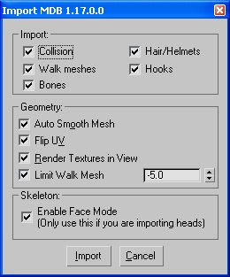
- When you load the model, you’ll see what looks like a bunch of spheres and lines with a ghoul head somewhere in the mix. Although it’s not obvious at this point, there are actually three ghoul heads superimposed over each other. A lot of these objects are getting in the way of our modding. We’ll want to hide all of them except for the ghoul head with the highest poly count as well as the bones (the ones that look like thin lines forming a complicated sort of stick figure).

Click the “Display” tab at the upper-right side of the screen. It’s the one with a computer monitor icon. Make sure that the ghoul head is selected. If it isn’t, click on it first.
Now click the “Hide by Name…” button that is located under the “Hide” rollout. (Need a hint to its location? Refer to the bottom thirds of the above picture.)
A window named “Hide Objects” will appear. Scroll down the list of objects until you find the ones named “COLS00” to “COLS12.” These refer to the collision spheres, which are the ball-like objects that surround the ghoul’s skeleton. To hide them, click “COLS00” in the list then press the [Shift] key and click “COLS12.” All the collision spheres will be selected. While holding down the [Ctrl] key, click the objects named “C_Ghoul_Head01_L01” and “C_Ghoul_head01_L02.” These are lower-poly versions of the ghoul head. Since we don’t want them getting in the way, we’ll need to hide them as well.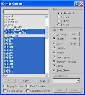
Now click the “Hide” button, and you’ll be left with the main ghoul head as well as the skeleton itself.


Studying the Bones
- Click the “Display” tab. In the “Parameters” rollout below the word “Bones” is a list of bones that affect the ghoul’s face. Copy this list somewhere. You’ll need it later.

- Let’s take a closer look at the ghoul’s ugly mug. Change the Front viewport to show the back view instead. Use the Pan tool (the one with the hand icon) to center the head as you zoom the view with your mouse wheel. (Don’t have a mouse wheel? You’ll have to alternate between using the Pan tool and the Zoom tool. The latter’s icon looks like a magnifying glass and is located above and to the left of the Pan tool.)
Press the [F3] key to switch from wireframe mode to smooth + highlights mode. You’ll see the ghoul’s face rendered in all its glory.
Do the same for the Top view and the Left view to get a rendered close-up of the ghoul’s head in these viewports. - We’ll want to see what regions of the head each bone affects, but it would be better to disable textures for now. Go to the “Views” menu and click the option “Deactivate All Maps.” A window will appear, warning you that the “Show Map in Viewport” flag will be disabled. That’s precisely what we want to do, so click the “Yes” button.

It may seem at first that all of the textures are still being rendered. If you click any of the viewports, however, the textures will be replaced with gray. - Under the word “Parameters” in the “Modify” panel is a button labeled “Edit Envelopes.” Click it.
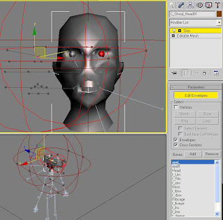
Now take a look at the list of bones below the Parameters (also in the “Modify” panel). When you click the bone labeled “eyeL”, you’ll see that the ghoul’s left eye turns red. That means that the “eyeL” bone controls the ghoul’s left eye. If you click the bone labeled “eyeR,” it will be the ghoul’s right eye that will turn red.
In fact, clicking each bone in turn will cause a different region of the head to become colored. The colors are an indication of how much weight the bone has in each vertex of the head. Red means that the bone’s influence over the affected vertices is strong. Orange means that the bone shares influence over the affected vertices with one or more other bones. Yellow means that the bone’s influence is weak, and blue means that its influence is even weaker.
Go over each bone in the list you made and click each one in turn. Note what general regions of the head each bone affects. Be sure to put it in writing because you’re unlikely to remember them all. Check out each viewport because some regions aren’t visible in all viewports.
When you’re done, switch back to wireframe mode in all viewports by clicking each of them in turn and pressing the [F3] key.


Replacing the Head
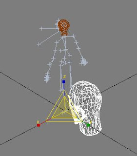
- Import the creature model that you last exported as an OBJ file. (It’s the one that was made in my last blog post.) You’ll have to set the file type to “WaveFront Object (*.OBJ)” to import the mesh. When the “OBJ Importer” dialog window appears, click the “OK” button.

We’re in for a surprise. The head we created is much bigger than expected. Also, it’s halfway in the ground. We’ll have to scale and position it properly.
- Click the oversized head to select it then right-click it. From the context-sensitive menu, select “Scale.” You’ll see a yellow triangle with colored lines that extend from two or three corners depending on which viewport you’re looking at. These lines are labeled “x,” “y,” and “z.” Ignore them. Instead, bring your mouse cursor to the center of the triangle and click-and-drag to resize the head. You may have to do this several times to get it to the right size. It’s unlikely that you’ll have it done perfectly in one go.
- When you think you’ve scaled the head correctly, right-click on it and select “Move” from the context-sensitive menu. Superimpose the head over the ghoul’s head by clicking-and-dragging the head or the green, red, and blue arrows. You’ll want to do this at each viewport to make sure that the head is positioned properly in three-dimensional space. You may zoom in with your mouse wheel to fine-tune the positioning of the head. (Again, if you don’t have a mouse wheel, you can use the Zoom tool instead, but you’ll have to switch to the “Select and Move” tool afterward.)

- Click the old ghoul head and press the delete key. Now that we have a new head, we don’t need the old one anymore.


Making It a Skin Mesh
- Since we’re effectively creating a temporary replacement for the original ghoul head, we’ll have to rename the mesh accordingly. The name of the head must match the name of the MDB file. Select the mesh and right-click it to bring up the context-sensitive menu. Click “Properties.” When the “Object Properties” window appears, click the text box labeled “Name” and type “C_Ghoul_Head01” without the quotation marks.

- While still in the “Object Properties” window, click the tab labeled “User Defined.” Under “User Defined Properties,” type the following:
UIFlag = Alpha_Test | Cutscene_Mesh
Skeleton = c_ghoul_skel
The UIFlag property controls how the NWN2 engine will render the mesh. There are eight possible values of UIFlag, each of which is interpreted as a bit flag, which is the number 2 raised to some power. (Not that you needed to know that.) What may be important to know is that different values can be joined together using the “|” (pipe) symbol. Anyhow, the values of UIFlag may be any of the following:- None = 0 (aka trans = 0)
- Alpha_Test = 1 (aka trans = 1)
- Alpha_Blend = 2 (aka alphablend = 1) #### SHOULD NOT BE USED
- Additive_Blend = 4 (aka addblend = 1) #### SHOULD NOT BE USED
- Environment_Mapped = 8 (aka envmap = 1)
- Cutscene_Mesh = 16 (aka head = 1)
- Glow = 32 (aka glow = 1)
- No_Cast_Shadows = 64 (aka nocast = 1)
- Projected_Textures = 128 (aka projtex = 1)
(I copied this info from tazpn’s description of the 3ds Max MDB Importer/Exporter.)
If all this information sounds as cryptic to you as it does to me, just set the UIFlag of your head models to “Alpha_Test | Cutscene_Mesh,” and you’ll be fine.
The Skeleton property defines which skeleton to use. Its value is the name of the applicable skeleton file without the GR2 extension.
Anyhow, enough talk. Click the “OK” button in the “Object Properties” window and move on to the next step. - The head mesh won’t animate unless we first transform it into a skin mesh. To do this, go to the “Modifier” panel and bring up the modifier list. From there, click the modifier named “Skin.” This effectively transforms the model into a skin mesh.


Attaching Bones
- While still in the “Modifier” panel, click the “Add” button that is beside the word “Bones.” Now take out the list of bones that you made earlier. These are the bones that may affect the movement of the head mesh. In the dialog window, press [Ctrl]+click on each bone that appears in your list. When you’re done, click the “Select” button.

- Now comes the hard part. We’re going to set how much influence each bone has on each vertex. The “influence” that a bone has over a vertex is called its bone weight. There are several ways to set these weights. We’ll use three such methods.
The first method is to wrap envelopes around the affected vertices. Envelopes define the regions of the mesh over which the associated bone has influence. Envelopes look sort of like wireframes shaped liked a couple of concentric lozenges. We can change the length of the lozenges as well as their diameter at each end, but we cannot change their shape. If the mesh is complicated, it may not be possible to wrap envelopes around all the vertices to be affected without wrapping them around vertices that we do not want to include. No matter. We’ll use the other two methods of weighting vertices to fine-tune our initial set of weights.
In the “Modifier” panel, make sure that the “Skin” modifier is selected then click the “Edit Envelopes” button. Notice the concentric lozenge-shaped wireframes in the viewports. You’ll see that some of the vertices are colored in accordance with their bone weights. These initial settings are bound to be wrong, so we’ll have to wrap envelopes around the vertices ourselves.
- In the list of bones that appears in the Parameters rollout, click the bone that is labeled “Head.”

Look at how the Head envelope initially appears in all four viewports. Not only are they off-center, but they are also much too large.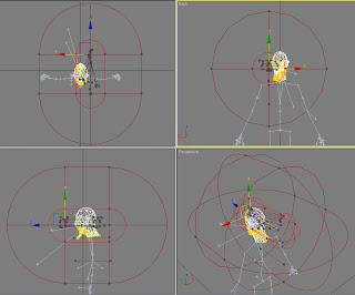
- Use the “Select and Move” tool to adjust the length and diameters of both the inner envelope and the outer envelope. The envelope must encompass the entire head but should ideally not go beyond the point where the cranium meets the neck. Don’t worry about wrapping the envelope too precisely, though. We’ll adjust the bone weights later.
Look at the screenshot below. By the time I was done wrapping the envelope around some of the vertices, the viewports showed that parts of the neck were within the Head envelope. We’ll correct that later. For now, let’s move on to the other bones and wrap their envelopes around the appropriate regions of the mesh.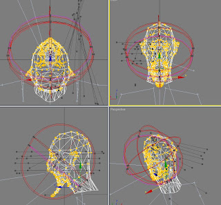
When you’re done wrapping envelopes, move on to the next step. - Another technique for weighting bones is to “paint” weights on the vertices. Perhaps the best way to learn about this technique is to try it out. As before, the “Edit Envelopes” button will have to be activated. You can’t paint weights otherwise.
In the “Modifier” panel, click the “Paint Weights” button. You may have to scroll down the panel to see it.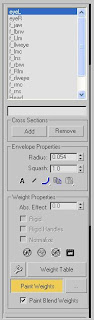
Beside the “Paint Weights” button is another button with an ellipsis (“…”) on it. Click it to access the “Painter Options” dialog box. Look at the box beside the label “Max. Size.” By default, the value in this box is 10.0. Change it to a much smaller number such as 0.02. This effectively decreases the size of the “brush” to a more manageable level. If you want repeated brushings over the same area to strengthen the bone weight there, make sure that the box beside “Additive” is checked. Close the “Painter Options” window when you are done.
In this example, we’re going to paint the weights for the bone f_jaw. When I wrapped the f_jaw envelope around my model, I felt that the right side of the jaw may not be adequately controlled by the f_jaw bone. I also felt that the influence of the bone on the jaw region was too weak overall. I switched my Left viewport to show the right side of the model and pressed [F3] to switch on smooth + highlights mode.
By “painting” over the vertices, I was able to extend the influence of the f_jaw bone. I was also able to strengthen the bone’s influence on the right side.
- The last weighting technique that I’ll discuss involves the weight tool. Before using it, go to the “Parameters” section of the “Modifier” panel and make sure that the “Edit Envelopes” button is pressed and that the box labeled “Vertices” is checked.

Next, select a group of vertices whose bone weights you want to adjust by clicking-and-dragging your mouse cursor over them. In this particular case, I want to adjust the weights of the neck area, so I click-and-drag over the neck. In the example shown below, I wound up selecting not only the vertices of the neck but also parts of the ears and cheeks. I can de-select vertices by pressing the [Alt] key while clicking-and-dragging over the unwanted vertices. I can also add vertices by pressing [Ctrl] and clicking-and-dragging over the vertices I want to add. It may be necessary to look at the selection from different viewports to make sure that only the vertices we want to weight are selected.
Next, click the weight tool button. It’s the button beside the one that says “Weight Table,” the one with an icon that looks like a wrench. When you click the button, the “Weight Tool” dialog box will appear.
For the vertices I selected, I want to set the weight of the Neck bone to 1.0. First, I have to select the Neck bone. If it appears in the Weight Tool, such as what is shown in the above picture, I can click the word “Neck” in the dialog window. Otherwise, I’ll have to click the one that appears in the list of bones in the “Modifier” panel. Now I can set the bone weight. One way to do this is to enter the number “1.0” in the box beside the “Set Weight” button. I can then click this button to set the weights. There are other ways to do this, but I’ll leave it to you to figure out. (Hint: the buttons with numbers in them might mean something.) - Continue to fine-tune the bone weights of the vertices until you’re ready to test them. One way to do this is to move the bones in 3DS Max and see if any vertices start getting unruly. To select a bone to move, press the [H] key, select a bone from the “Select Objects” dialog box that appears, and press the “Select” button. In this particular example, I want to test the vertices with respect to the f_jaw bone, so I click “f_jaw” in the list then press “Select.”

At this point, there will be arrows that appear at each viewport. Clicking-and-dragging these arrows will move the f_jaw bone.
Let’s see what happens when I move the bone in this example.
Sweet Cyric on a pogo stick! Looks like I didn’t weight my vertices properly.
Weighting vertices is easily the most time-consuming task when it comes to modeling creatures and armor. Ferreting out unruly vertices and putting them in their place often takes a lot of work.


Simplistic Texturing
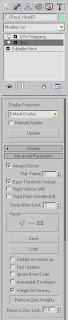
- The iron test for checking if the vertices are weighted correctly is to test the model with the NWN2 engine. The model won’t display without diffuse and normal textures, however, so we have to make a rudimentary UVW Map and assign placeholder textures to the mesh.
UVW Maps are how graphic engines know which pixel in a texture map goes to which part of a 3D mesh. We don’t have time to delve deeply into this topic right now. All we want to do is to check if we’ve rigged the bones to our skin mesh correctly.
Let’s apply a fast mapping method: From the Modifier List, click the “UVW Mapping” modifier. In the Mapping Parameters, click the radio button labeled “Cylindrical” then press the “Fit” button. The model now has a UVW map.
The diffuse texture we’ll apply is a 128 × 128 swatch of gray. The normal texture is basically converted from the diffuse texture using either nVidia's Photoshop plug-in or the CrazyBump software. Both textures are DDS files.

To apply these textures to the model, bring up the Material Editor by pressing the [M] key. Expand the “Maps” rollout by clicking its “+” sign.
Click the checkbox labeled “Diffuse Color” then click the button labeled “None.” This will bring up a window called the “Material/Map Browser.”
Double-click the word “Bitmap,” which appears at the top-right side of the window. This will bring up another window that will prompt you to select a bitmap image file. Navigate to where the diffuse map is stored, click the name of the file, then press the “Open” button. The window will then close.
Next, we have to add a normal texture to the same material. In the Material Editor, click the “Go to Parent” button, which is the second-to-the-last button below the picture of the six spheres.
At the “Maps” rollout, click the checkbox labeled “Bump,” and use the same process that we did for choosing a diffuse texture, but this time, choose the normal texture instead. When you’re done, click the “Assign Material to Selection” button then click the “Show Map in Viewport” button. If you’re not sure where these buttons are, just hover your mouse cursor over the tiny icons below the spheres until you find the tooltips that identify the buttons you need to press.
You may now close the Material Editor.


Testing with NWN2
- Next, export the model as an MDB file named C_Ghoul_Head01.MDB. If you’re saving this in your working folder, you’ll probably wind up overwriting the copy of the file that is in it. That’s all right, go ahead and do it.
Save your work as a MAX file as well. We'll be returning to it later. - Now copy the newly saved MDB file, as well as its diffuse and normal texture files, to your NWN2 Override folder. For most Windows XP users, that folder would be “My Documents\Neverwinter Nights 2\override”.
- The moment of truth is now upon us. Run the Neverwinter Nights 2 Toolset and create a small exterior area. Put a ghoul in it. Since the head we’ve created replaces the ghoul’s head, we should see the new head on top of the ghoul’s body.

In the model shown above, there are a few holes where the neck connects with the body, but that’s fine with me. I’ll be making a new body for this creature anyway.
If you made a mistake in rigging the model, you'll probably see some problems with it at this point. Among the potential problems that you might find are the following:- The model does not appear.
- The model freezes in place instead of running its idle animation.
- The head is not sized correctly.
- The head is not positioned properly.
- Polygons are protruding like jagged spikes around the model.
If any of the above occurs, you’ll have to fix the problem in 3DS Max.

Removing Zero Weights
- Once you are satisfied with the way you’ve rigged the bones to the skin mesh, there’s one last thing you can do to decrease the size of the MDB file somewhat. In 3DS Max, make sure that your model is selected. Click the “Modify” tab to bring up the “Modify” panel then click the model’s "Skin" modifier. Scroll the panel all the way down and click the “+” sign beside “Advanced Parameters” to expand the rollout. Now click the button labeled “Remove Zero Weights.” This will remove unnecessary data pertaining to bone weights with zero values.
Save your file both as a MAX file and as an MDB file. Congratulations. You’ve just survived one of the toughest parts of 3D modeling.

If you’ve read this blog post from start to finish, you probably intend to create your own creature models. If so, good for you. I hope to see your submissions at the Neverwinter Vault. Nevertheless, we’re not done yet. I haven’t explained how to texture models properly. Unless you’re happy with giving your creatures a bland, gray look, you may want to know more about texturing. That will be the topic of my next three blog posts, so stay tuned.


Comments
Thanks again, Frank!!