Creature Modeling, Part 2: Bringing the High-Poly Model Low
This is a continuation of my series on building creature models for NWN2. Those who haven’t read the start of this series may want to refer to my previous blog post.
Having created a very high-poly model in ZBrush, I have to bring down the number of polygons to a more playable level. My model had 24,578 vertices and 49,152 polygons at the start. I wanted to bring the number of polygons to below one thousand. The following steps show how I did it.
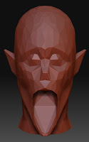
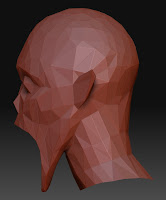
After a painstaking process of reducing polygons and adjusting vertices, I eventually brought my model down to 471 vertices and 927 polygons. The pictures below show how the model looks in ZBrush.
Over the next several days, I continued to work on the model, eventually reducing the polygon count to 840 but at the cost of increasing the number of vertices to 523.
My next blog post in this series will show how to transform this mesh into an actual creature head that can be viewed from the toolset or in game. Stay tuned.
- Author's Note, January 20, 2009: Since posting this write-up, I found a better way to reduce vertices in a mesh. Originally, I made indiscriminate use of the Optimize modifier, but I found that the MultiRes modifier worked better on my model. I rewrote this blog post to reflect my new workflow.
Having created a very high-poly model in ZBrush, I have to bring down the number of polygons to a more playable level. My model had 24,578 vertices and 49,152 polygons at the start. I wanted to bring the number of polygons to below one thousand. The following steps show how I did it.
- Import your model in 3DS Max. To do this, click the “File” menu and select “Import…”. In the dialog window, navigate to the folder where you stored your model file. In the “Files of type” box, select “WaveFront Object (*.OBJ)”. Click the name of the file that you had exported earlier and click the “Open” button.

The “OBJ Importer” dialog window will then appear. Just click the “OK” button.
- When the model is loaded into the program, you will see four different views of the model; namely, Top, Front, Left, and Perspective. The Front view is actually a view of the model from behind. (Don’t ask why.) If you want to see the model’s face, you can right-click the word “Front” in the upper left corner of the Front viewport, position the cursor over the “Views” submenu, then click “Back”. You can change any of the views by right-clicking the name of the view in the viewport that you want to change.

- Because the model is displayed as a wireframe in all but the Perspective view, it’s hard to tell how the model looks when rendered. If you want to preview the model, click on the view that you want to use and press the [F3] key. This key switches between wireframe mode and smooth + highlights mode. For now, let’s keep all but the Perspective view in wireframe mode.

- If the model isn’t centered in one of the viewports, you can adjust the view with the “Pan View” tool. This is located at the bottom-right corner of the screen. When you click it, the mouse cursor changes to a hand icon, which you can click-and-drag over a viewport to reposition the view.

When you’re done positioning the view, click the “Select Object” icon toward the top-left of the screen to restore the mouse cursor. This icon looks like an arrow pointing upward and to the left. Alternatively, you may click the “Select and Move” icon, which looks like a cross made up of arrows.
- Now that the viewports have been adjusted, we can begin the actual process of decreasing the polygon count. First, select the model by clicking it at any of the viewports. Next, click the “Modify” tab at the upper-right portion of the screen to bring up the “Modify” panel. This is where we’ll be doing most of the polygon-reduction work.

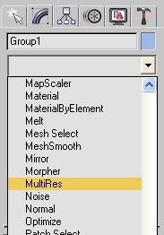
- Click the downward-pointing arrowhead at the box labeled “Modifier List” and click the word “MultiRes” in the drop-down list. This will put the MultiRes modifier on top of the Editable Mesh in the modifier stack.
- In the “MultiRes Parameters” rollout, click the “Generate” button and set a checkmark in the box beside “Vertex Merging.” Set “Vert Percent” to a suitably low number then click the “Generate” button again. This will reduce the number of vertices and faces (i.e., polygons) in the mesh.

Notice that the vertices and polygons are no longer symmetrical. We’ll try to restore symmetry to the model, but first, we need to know which side looks best.
- Click the Back viewport to select it and press [F3] to render the model. Choose whether to mirror the left or right side of the model to its opposite side. I preferred the right-side of the model (in other words, the one to the viewer’s left), so this is what I chose to retain. Press [F3] again to return to wireframe mode.

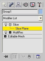
- Go to the modifier list and add the Slice modifier. (You may have to click the model first in case it isn’t currently selected.) When you've done this, click the “+” sign before the word “Slice” and click “Slice Plane.”
- If you look at the viewports, you will see a square-shaped plane cutting across the model. (In some viewports, the plane will appear as a line.) You’ll need to position the plane to cut between the left and right sides of the model.

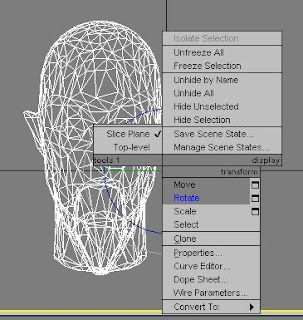
- At the Back viewport, right-click on the plane and click “Rotate” on the context-sensitive menu.

- At the bottom of the screen, you will find three text boxes labeled “X,” “Y,” and “Z.” These constitute the Absolute Mode Transform type-In. We want to make the slicing plane vertical, so enter “0” in the textbox labeled “Z.” (You may also use the mouse to rotate the plane in the viewports, but the entering a number is more accurate.)

- Right-click the plane and select “Move” from the context-sensitive menu.
- Move the plane so that it completely bisects the model. Although you may do this by clicking-and-dragging the mouse over the plane, I prefer to type numbers in the Absolute Mode Transform Type-In. For this model, I set X to 0.5, Y to -0.5, and Z to 0.15.

- On the “Modifier” panel, click either the “Remove Top” or the “Remove Bottom” button, whichever gets rid of the unwanted side of the model.

- Click the “Modifier List” button to bring down the list of modifiers. From there, select “Mirror.”

- Under the parameters for the Mirror modifier, set “Offset” to 1.0 and click the “Copy” checkbox. This will create a mirror copy of the mesh and place it in its opposite side.

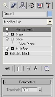
- From the Modifier List, select “Vertex Weld,” set its “Threshold” parameter to 0.01, and press Enter. This ought to connect the two halves of the mesh into one whole.
- In case holes were accidentally created in the process, add the “Cap Holes” modifier from the Modifier List. Just leave the default parameters as is.

- Export the mesh as an OBJ file. First, click the “File” menu, then click “Export…” In the dialog box, navigate to the folder in which you want to save your model. In the “Save as type” box, select “Wavefront Object (*.OBJ).” Type in an appropriate file name and press the “Save” button. In the “OBJ Exporter” dialog box that then appears, hit the “OK” button without changing any parameters.

If you wish, you may also save your work as a MAX file. Just click the “File” menu, select “Save As…”, and do what comes naturally. - The process of decreasing the number of polygons may have changed the appearance of the model in ways that you do not want. You may tweak the position of the vertices to adjust the appearance of the mesh. While this can be done in 3DS Max, ZBrush makes it easier to do.
Load ZBrush and select the “Open Model (OBJ or ZTL)” option that appears when the program starts up. Navigate to the folder that contains the OBJ file that was exported and select it for loading. By default, left-right symmetrical editing is turned off for imported OBJ models, so press the [X] key to turn it on. Use the Tweak brush to adjust the vertices to your liking. When you are done, export the model to a new file.
- At this point, the mesh may still have too many polygons to be usable in game. You may repeat the above steps until the polygon count is low enough for you.
In addition, you may also select a group of vertices and weld the ones that are closest to each other. To do this, go to the Modifier List, click the “+” sign beside “Editable Mesh” in the list of modifiers, and click “Vertex.”
You can click-and-drag over any of the viewports to select a group of vertices. If you’ve selected too few vertices, you can add to your selection by pressing the [Ctrl] key while clicking-and-dragging over more vertices. If you want to take away some vertices from your selection, hold down the [Alt] key while clicking-and-dragging over the vertices you don’t want to include. When you’re satisfied with your selection, go to the “Edit Geometry” rollout in the Modifier panel. Under the word “Weld” is a button marked “Selected.” Beside it is a box that has a default value of 0.1. Change this figure to some lower value such as 0.01 then click the “Selected” button. This will weld the vertices in the selection that are within 0.01 units from each other.
When you're satisfied with the appearance and polygon count of your model, export it as an OBJ file.


After a painstaking process of reducing polygons and adjusting vertices, I eventually brought my model down to 471 vertices and 927 polygons. The pictures below show how the model looks in ZBrush.


Over the next several days, I continued to work on the model, eventually reducing the polygon count to 840 but at the cost of increasing the number of vertices to 523.
My next blog post in this series will show how to transform this mesh into an actual creature head that can be viewed from the toolset or in game. Stay tuned.


Comments
You might want to look at a Max plugin called PolyChop. Use it as an alternative for the Optimise modifier. PolyChop gives you a little more control over the poly reduction process.
@Barry the Hatchet,
Thanks for the tip on the PolyChop plugin. I'll be sure to look it up. If you have any more tips or even constructive criticism to share, please feel free to write them at the comment pages. I'm always happy to learn from veteran modelers.