Creating New Life with the Expotron and Max, Part 5: Rigging and Exporting Creature Models
This is Part 5 of my tutorial on bringing new creatures to NWN2 using 3DS Max and the Expotron. Part 1 of this series may be found here.
With the preliminaries out of the way, we can now proceed with the tutorial proper. Fire up 3DS Max, load your creature model, and follow the instructions below.
In my next, concluding blog post in this series, I will show how to animate NWN2 models.
With the preliminaries out of the way, we can now proceed with the tutorial proper. Fire up 3DS Max, load your creature model, and follow the instructions below.
- Make sure that the pivot of each mesh is centered at world coordinate (0,0,0). This pivot is what defines the creature’s center, which NWN2 uses to calculate distances between objects. Assuming you haven’t rigged the mesh yet, click the Hierarchy panel (the one whose icon looks like an organizational chart on the upper right side of the screen) then click the button “Affect Pivot Only.” Next, click the Select and Move tool, and in the Absolute Mode Transform Type-In (the three input boxes at the bottom of the screen), set the X, Y, and Z values to 0,0,0. Toggle the “Affect Pivot Only” button when you’re done.

- To rig the mesh, we are first going to make its skeleton. If you have any LOD meshes, hide them for now. We will work only with the main meshes, but we’ll need them to be transparent so we can see the bones underneath. Select your meshes and right-click on them to bring up the context-sensitive menu. Click Properties to bring up the Object Properties window. Tick the check box beside “See-Through” then click the OK button.

- We will now make the root bone for the body mesh. We need it to be at the center along the left-right axis, so make either the Left or Right viewport active by selecting it. If you wish, you may toggle viewport maximization by pressing [Alt]+W after selecting the viewport you want to work in. On the Create panel, click the Systems icon, the one that looks like a couple of gears. Click the Bones button then click within the mesh not too far from where you want your root bone to be. Move the mouse to the desired position of the root bone then click the mouse again. This will create one bone. Now right-click the mouse to end bone construction. This will create a second bone, which is really just a small nub. It is this tiny bone that we want to make the root bone, not the first bone. Rename it in accordance with the skeleton naming convention explained earlier.

- We won’t need the first bone anymore, so select it and delete it. We should be left with only the root bone of this skeleton.

- We’re going to build up the rest of the skeleton for this mesh. Select the root bone and click the Bones button under the Create Systems panel. Click the root bone again to create a new bone that connects to it and click on the spot where the new bone ends. You can create another bone that connects to the last one that you made by clicking on the spot where the new bone ends. Continue in this manner until you’ve completed the bones for the body and head mesh. Make sure that you don’t make more than fifty-four bones. If you need to stop making a chain of bones to build a new chain in another part of the creature, right-click the mouse to end the bone creation process. This will create a nub bone at the end of the chain. If the creature you’re making will need more than one skeleton hierarchy (say, to bypass the fifty-four bone limit for each skeleton), don’t delete the nub bone at the juncture between the meshes. You should, however, delete the nub bones that are not intended for use as root bones in other skeletons.

Remember to use the Left or Right viewport if you want to center the bones along the left-right axis. If you want to create arms or legs, however, you will have to switch to the Front or Back viewport. Start on just one side first so you can clone the bones for the other side later. For example, to build the right arm and shoulder, you may select the part of the spine where the right shoulder connects then click the Bones button to start creating new bones. Click the selected part of the spine again, which is where the right shoulder will begin, and then click the spot where the right shoulder ends. From there, create bones for the upper arm, lower arm, and fingers. When you’re done and have deleted any unnecessary nub bones, select all the bones from the shoulder to the fingers and clone them as a copy (not as an instance). Select the cloned shoulder and rotate it 180 degrees along the left-right axis. This will give you a set of bones from the left shoulder down to all the fingers on the left side. - If your creature has another mesh that will need its own skeleton hierarchy, select the nub bone that you intend to make the root bone of the new skeleton. Clone this bone as a copy and change the name of this bone to correspond with the naming convention for the type of skeleton you’re making. Don’t delete the original nub bone. It should remain a part of its skeleton.

- With the cloned bone selected, click the “Unlink Selection” button, which is somewhere on the left side of the top toolbar just below the Group menu. This will separate the cloned bone from the hierarchy, thereby allowing you to make it the root of a new skeleton.

- Make sure that the new root bone is still selected then click the Bones button under the Create Systems panel. Click the root bone to start creating a new bone that is linked to it and click on the spot where the new bone ends. Keep building bones until you’ve completed the skeleton. Make sure that the skeleton hierarchy does not exceed fifty-four bones.

Two completed skeletons, one for the body and one for the "wings" mesh, which is actually the hydra's five heads and necks - If you have a third mesh that needs its own skeleton, repeat steps 5 to 7 for that skeleton until you’ve completed it. Remember that each creature may have no more than three skeletons.
- We will now add attachment points to the creature. In the Create panel, click the Helpers button, whose icon looks like a measuring tape. Click the Dummy button to start creating dummy objects. Position the mouse where you intend to make the first attachment point then click and drag the mouse to make a small square. This will make the dummy object. When it comes to exporting the skeleton later, it doesn’t really matter how big or small you make the dummy object, but try to make it as small as possible to give you a better idea of where its center point is. Rename the dummy object to correspond to the appropriate standard name for the attachment point you’re creating. If necessary, you can reposition a dummy object with the Move tool. If you need to stop creating dummy objects, you may right-click the mouse anywhere on the viewport. Keep making and renaming dummy objects until you’ve completed all the attachment points your creature needs.

- Next, we will link each attachment point to the appropriate bone. Select an attachment point then click the “Select and Link” button, which is on the top toolbar just below the Tools menu.

Press [H] to bring up a list of objects to which you may link the dummy object. Click on the name of the bone you want to attach the dummy object to then click the Link button. Continue to select attachment points and link them to the appropriate bones until you’ve linked all of them.
When you’re done, access the Object Properties of each mesh, un-tick the check box marked “See-Though,” and click the OK button to close the Object Properties window. - Optional step: At any time, you may view your hierarchy of objects by clicking the “Schematic View” button on the top toolbar.

This will bring up a window showing your object hierarchy. Review it to make sure that all root bones are at the top of their own hierarchy and that all bones and attachment points are linked correctly. None of your meshes should be linked to any object. When you’re done looking at the schematic view window, close it.
- Now we will add collision spheres. These objects are named COLSxx, where xx is a two-digit number that starts at 00 and increments sequentially. The game engine uses a creature’s collision spheres to determine if it is touching any other object. The only data stored in MDB files on collision spheres are their name, position, radius, and what bone they are linked to. Data on polygons and vertices are not stored, so it’s all right to create collision spheres with 32 segments. What we want to do is to cover the model with as few spheres as necessary without covering spaces that are too far beyond the surface of the mesh. We don’t want to use too many spheres as this may bog down the game engine with unnecessary computations. Hence, we may create spheres that are somewhat larger than they would be if we sized the spheres to be close to the mesh’s surface. On the other hand, we don’t want to make the spheres so big that the game engine will think that the creature is colliding with some other object when it is obvious to the human eye that nothing is brushing its surface but the ground. How big to make each sphere and where to put it will require a subjective judgment call on your part. Don’t fret too much about it. This isn’t rocket science. At any rate, by the time you’re done, your model will be covered with many candy-colored spheres. Enjoy the festive atmosphere that these spheres bring because all this is about to change in a minute.

- Press [H] to bring up the Select Objects window. Select all the collision spheres in the list by clicking on the first sphere then with the [Shift] key held down, clicking on the last sphere. Click the Select button to close the window.

Right-click on any of the collision spheres to bring up a context-sensitive menu and click the Properties option. On the Object Properties window, tick the check box beside “See-Through” and un-tick the Renderable check box. Click the OK button when you’re done.
This will cause all your colorful spheres to become transparent gray objects. Looks like the party’s over.
- Select each collision sphere in turn and link it to an appropriate bone by using the Select and Link tool, similar to the way it was done with the attachment points. The sphere should move with the part of the mesh that it is intended to cover, so choose which bone to link the sphere to accordingly. Usually, this will be the bone closest to the center of the sphere. By the time you’re done, all the collision spheres should be linked to a bone.

- Optional step: You may want to bring up the schematic view again to make sure that no collision sphere is left unlinked.
- At this point, we’ve created one or more skeletons complete with attachment points. We’ve also covered the creature with collision spheres and linked them to the appropriate bones. Next, we’ll rig each mesh to its skeleton.
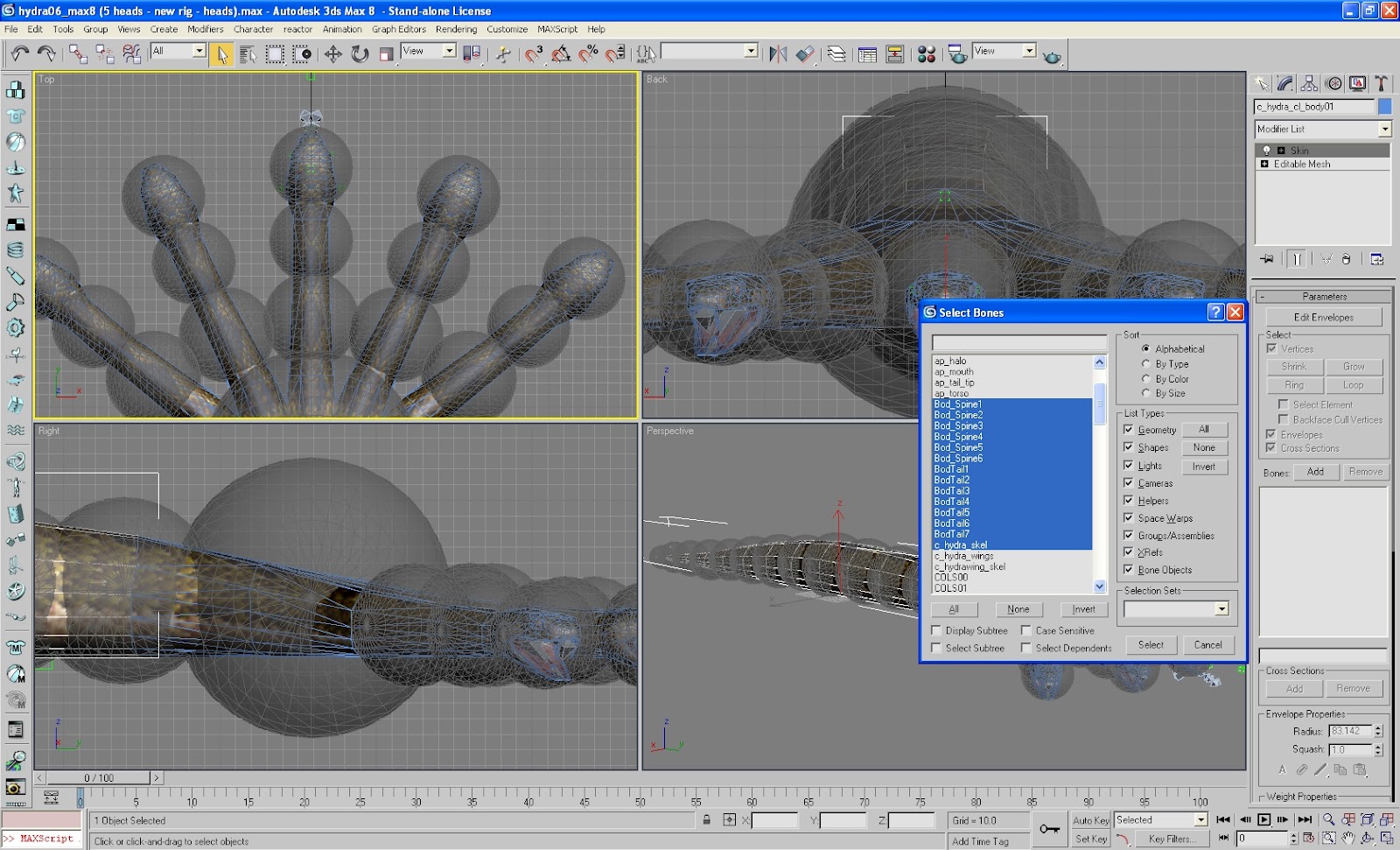
Click the Modify panel to access it. Select each mesh in turn and add a Skin modifier to it. For each mesh, click the Add button beside “Bones:” on the Modify panel and select all the bones from the skeleton hierarchy that is supposed to affect the mesh. You can select bones that are listed contiguously by clicking on the first bone that you want to select and with the [Shift] key pressed, clicking on the last bone. You can also select bones that are not listed contiguously by pressing the [Ctrl] key and clicking the bones to add. If your model has more than one skeleton, be sure not to add bones from outside the hierarchy that is supposed to influence the mesh. For example, if your model has three skeletons, the tail mesh should only be affected by the tail skeleton, and the wings mesh should only be affected by the wings skeleton. Also, do not add any attachment points as these are not supposed to affect your mesh. When you’ve chosen the bones of the appropriate skeleton from the list, click the Select button to add them. At this point, each vertex of your meshes will be provisionally weighted to one or more bones, although these vertex weights will likely be inaccurate. Nevertheless, you now have a quick and dirty rig.
- If you have lower LOD meshes, unhide them if they are hidden and repeat the above step for each of them.
- Optional step: If you want, you can weight the vertices more accurately to the bones and create the creature’s unarmed idle animation. If you’re like me, however, you’ll be anxious to see if your new creature will appear in the game. If so, you may defer the actual rigging and animation for later.
- We will now export the skeleton of your creature’s body. Press [H] bring up the Select Objects window and select all the bones and attachment points that belong to the body’s skeleton. Click the Select button to close the window. Now click the File menu and click the “Export Selected…” option. This will bring up a dialog window for selecting the file to export to. In the “Save as type” list box, select “Granny Run-Time (*.GR2).” Under File Name, type the name of the file you want to export the skeleton to. This file name should be the same as that of the skeleton’s root bone. Click the Save button.

- At this point, you should be looking at a dialog window named “Granny Export Settings.” Click the Models option under Settings. Make sure that the check box beside “Include reference in export” is ticked and the one beside “Move to Origin” is not ticked.

Double-click the word Models under Settings and click the name of your root bone. Again, make sure that the check box beside “Include reference in export” is ticked and the one beside “Move to Origin” is not ticked. You have to do this especially on your first time to export the skeleton because the dialog box has a tendency to keep the check box labeled “Move to Origin” ticked even when you un-tick it earlier.
Now, to be obsessively-compulsively sure that the check boxes are as they should be, double-click the name of the root bone and go through each bone in the hierarchy one by one, reviewing the state of both check boxes as you go along. When you’re done, click the Export button. If all goes well, you may then close the “Granny Export Settings” window.
- If you have other skeleton hierarchies, repeat steps 20 and 21 for each of them.
- Next, we’ll export the creature’s idle animation. If you skipped the optional step 19 above, your creature probably doesn’t have any kind of animation yet. That’s okay. We’ll export it anyway. When you view your creature in game, it will look as stiff as it does in 3DS Max, which is fine for our purposes.
Select all the bones and attachment points of your model. That’s right. All of them. If your creature has more than one skeleton, all their bones and attachment points should be selected. Click the File menu and click the “Export Selected…” option again. In the dialog box that appears, make sure that the list box labeled “Save as type” is still set to “Granny Run-Time (*.GR2).” In the “File Name” box, type the name of the animation you want to export. Standard animations have a naming convention that must be adhered to strictly. The name of the file to export should be the name of the root bone of the creature’s body but without the “_skel” suffix followed by “_idle.” Click the Save button.In the “Granny Export Settings” window that appears, click the Animations option under Settings. Make sure that the check box labeled “Include reference in export” is ticked and that the check box labeled “Move to Origin” is not ticked. Slide the Oversampling bar all the way to the right. Set Orientation Curve Tolerance to 0.15. When you’re done, click the Export button.

- Next we will export the creature’s meshes. Click the Utilities panel and click the “More…” button. In the Utilities window, select the “Expotron Utility” option then click the OK button. The Utilities panel will now have various Expotron utility settings to fiddle with.

Make sure that the skin mesh you wish to export is selected. Under NWN2 Types, click the “Character (skin)” radio button. Under “Skeleton Name,” type the name of the skeleton to which the skin mesh is rigged. (Recall that the skeleton’s name is that of its root bone.) If your model uses transparencies in the alpha channel of its textures, click the radio button beside “Transparency mask.” Otherwise, keep it set to “No Transparency.” If you have lower LOD versions of your mesh, give the same Expotron settings to each of them.
- Press [H] to bring up the Select Objects dialog box. Select all the collision spheres that are linked to your mesh’s skeleton along with the mesh itself. If you have lower LOD versions of your mesh, select those as well. Next, click the Select button.

Click the File menu and click the “Export Selected…” option. In the dialog box named “Select File to Export,” set the “Save as type” list box to “Neverwinter Nights 2 (*.MDB).” Under “File name,” type the name of your mesh. Click the Save button.
You should now see a dialog box named “Expotron Export Options.” Make sure that all the check boxes are ticked then hit the OK button. This will export your mesh to an MDB file.
- If your creature has other meshes, such as a wing mesh, a tail mesh, or both, repeat steps 24 and 25 for each of them.
- Make sure you have a copy of the file appearance.2da in your Neverwinter Nights 2 Override folder. Append an entry on your creature in the file and save it.

If you have a wing model or tail model to go with your creature, edit the appropriate 2da file to append an entry on it.
- And now, for the moment of truth. Create a test module and drop a creature in a new area. (I like using badgers for testing because they are already set to a faction that is friendly to player characters.) Change the creature's appearance to that of your model. Run the module and see if your model looks all right. If so, congratulations. All you have to do now is to weight the model's vertices in earnest and animate it.


In my next, concluding blog post in this series, I will show how to animate NWN2 models.


Comments
Lance.
I make an extensive use of the information contained here, thanks for sharing!
I'm glad you've found the information here useful. I don't mind having links to my blog posted at the new Vault or anywhere else for that matter, but I don't want the information here converted to a PDF.
There have been times when I would edit the information in my blog, especially when I've found out something new or when I've realized that old links don't work anymore. I prefer to keep this info in a format that I can edit myself if I have to.
I'll now create an entry to the new vault with all the links, thanks for the authorization to do so.